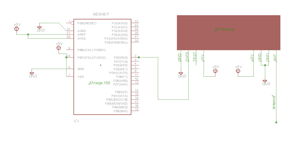
Link : http://narobo.com/articles/rfmodules.html


 Beta testers get a special discount on the Roboduino - $30 for the Roboduino kit ( thats 25% off of the retail price) and $50 for assembled board


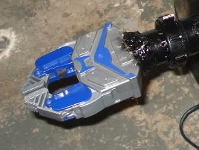
The robot arms will consist of a gripper and an arm which makes 90 degree revolutions.
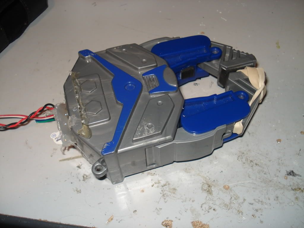
The gripper that I used came from one of those robot grabber toys.
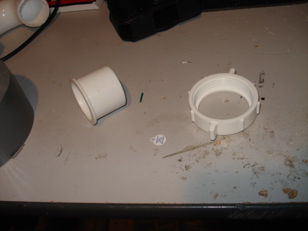
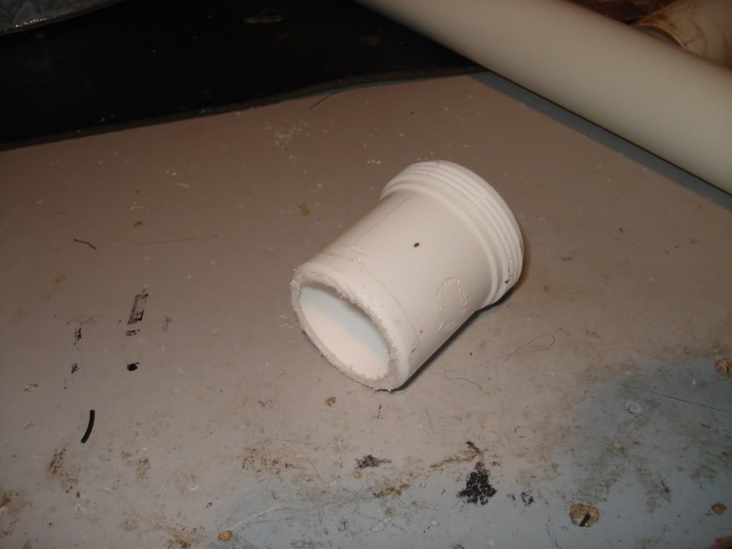
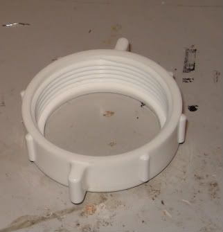
You will also need the following PVC parts , I believe one is called a threaded PVC connector and the other is a 2" length pipe with a piece of plastic sticking out in the back.
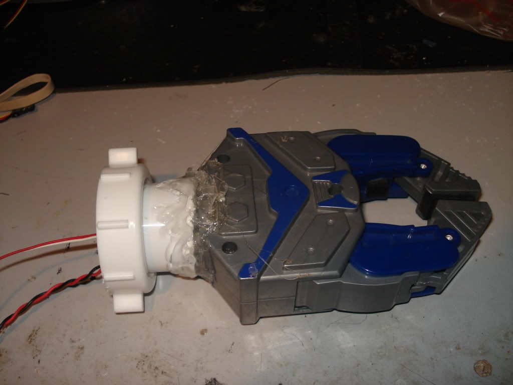
Put the threaded connector over the pipe piece and connect the end of that pipe to the gripper. Hot glue the end of the pipe to the gripper.
Now take any piece of PVC pipe that is threaded on the end and cut the pipe around three inches from where the threaded part begins.
Hotglue that piece that was just cut to the end of a different 17" PVC pipe.
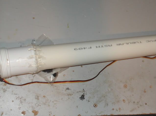
Now take both pieces outside and spray paint them black.After its dry you can attach the gripper to the pipe by just twisting the threaded connector on top of the threaded portion of the long PVC pipe.
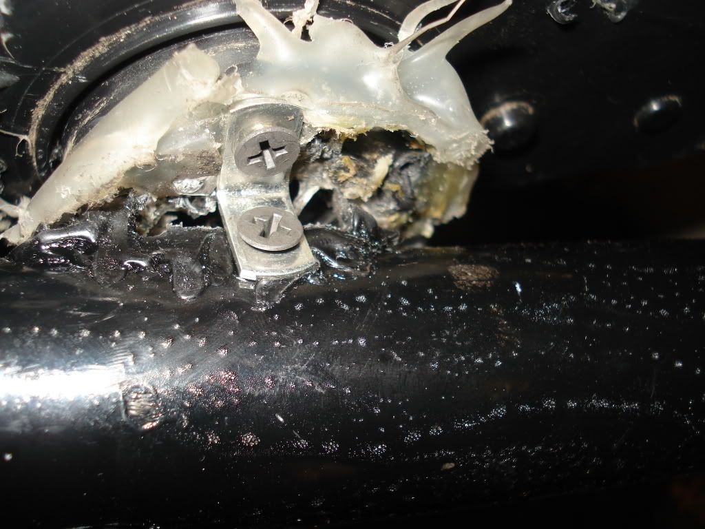
Now take one of the two Power Wheels motors and mount the long PVC pipe of the robot arm to it , using some small L brackets.Use hot glue if you want to secure it more. The small L bracket that I put was 7" from one end and 10" from the end with the gripper.
Now attach the motor to the body using two screws.
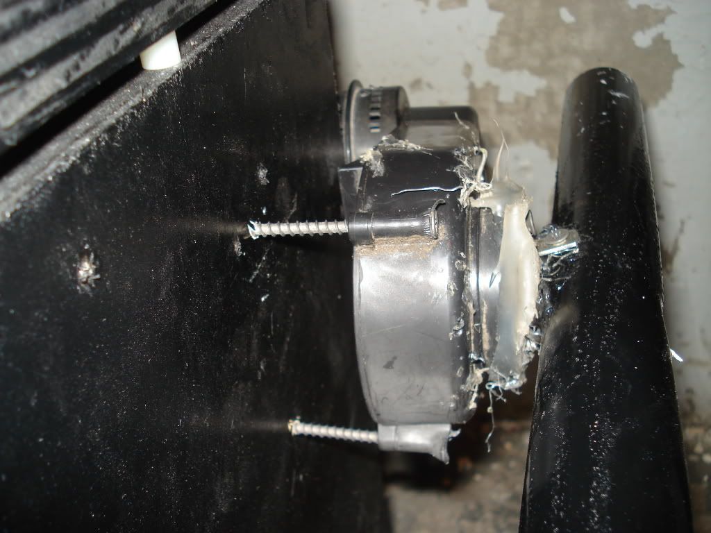
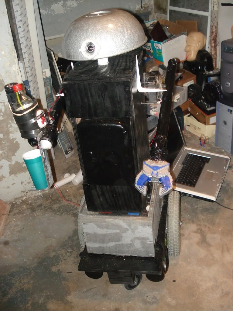
Your robot should now look like this
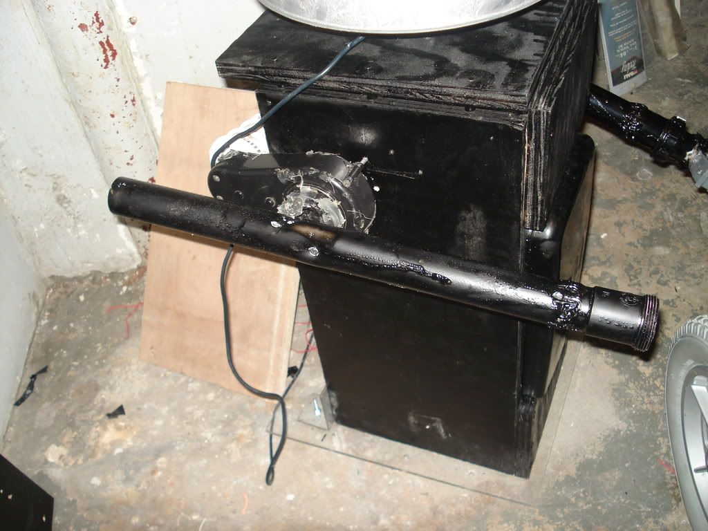
Take another piece of the same 17" PVC pipe and attach a threaded connector.
Spray paint that black and mount it to a motor with two small L brackets(one on top and one on bottom) as we did before to the other arm. Use hotglue if needed to secure the arm.
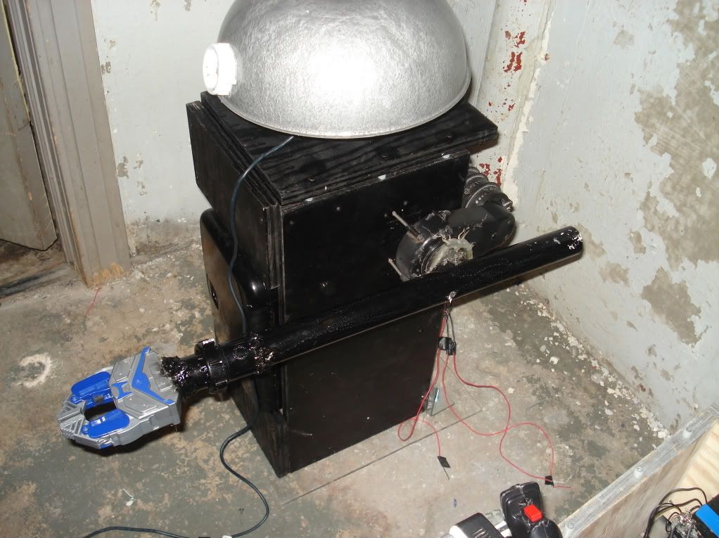
Make sure both arms are secured in place .Here is what you should have so far by the robot's body:
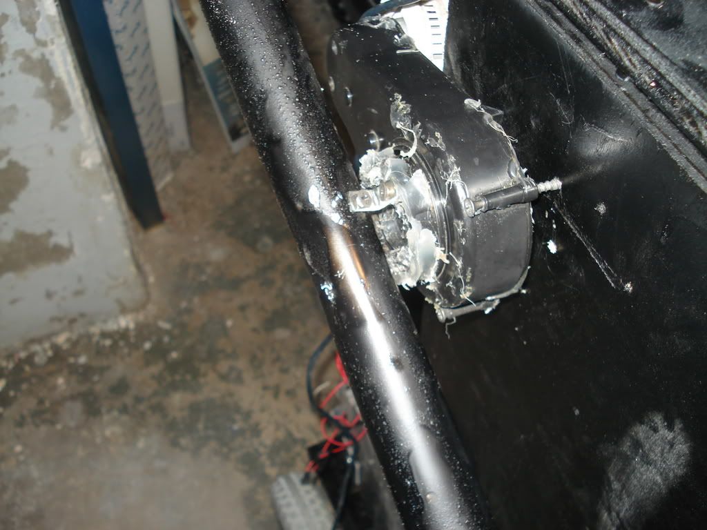
And the back view for those who need it:
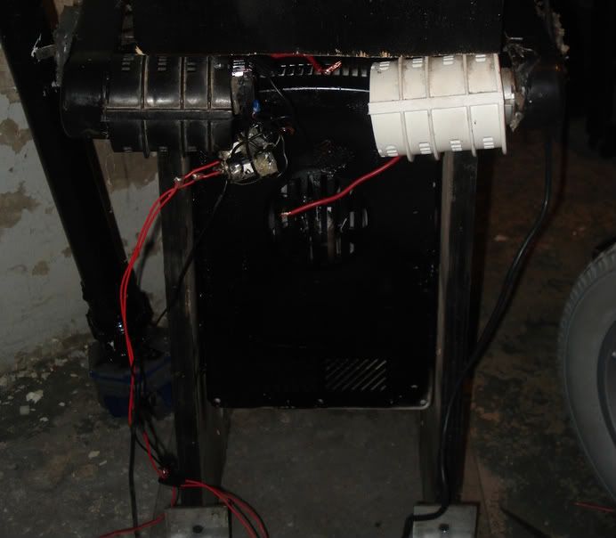
There should be two wires coming from each motors. Connect the red wires from each of the motors and connect those red wires to the positive terminal of the 6V battery pack.
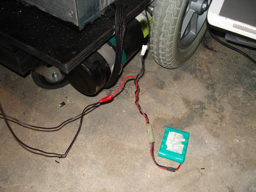
Connect the Negative terminal of that 6V battery to the negative of the 12V battery ( which is common ground) then connect the black wire of the left arm motor to Output #6 , and the black wire of the right arm motor to Output #7.
Solder on wires to the existing wires connected to the gripper and connect the red wire to the positive terminal of the 6V battery and the black wire to output #15.
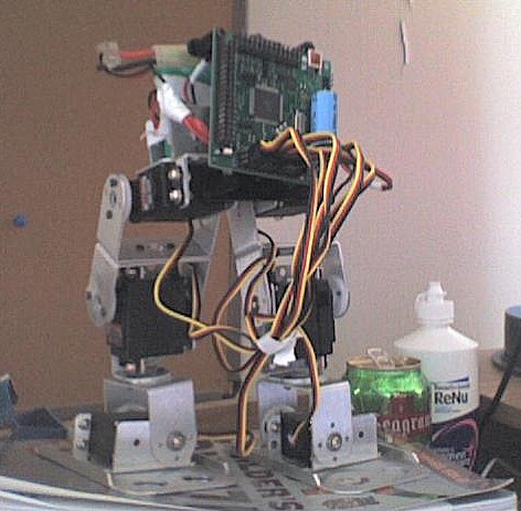
Open up the servo and solder on longer wires to the motor terminals. ( the red and black wires pictured)
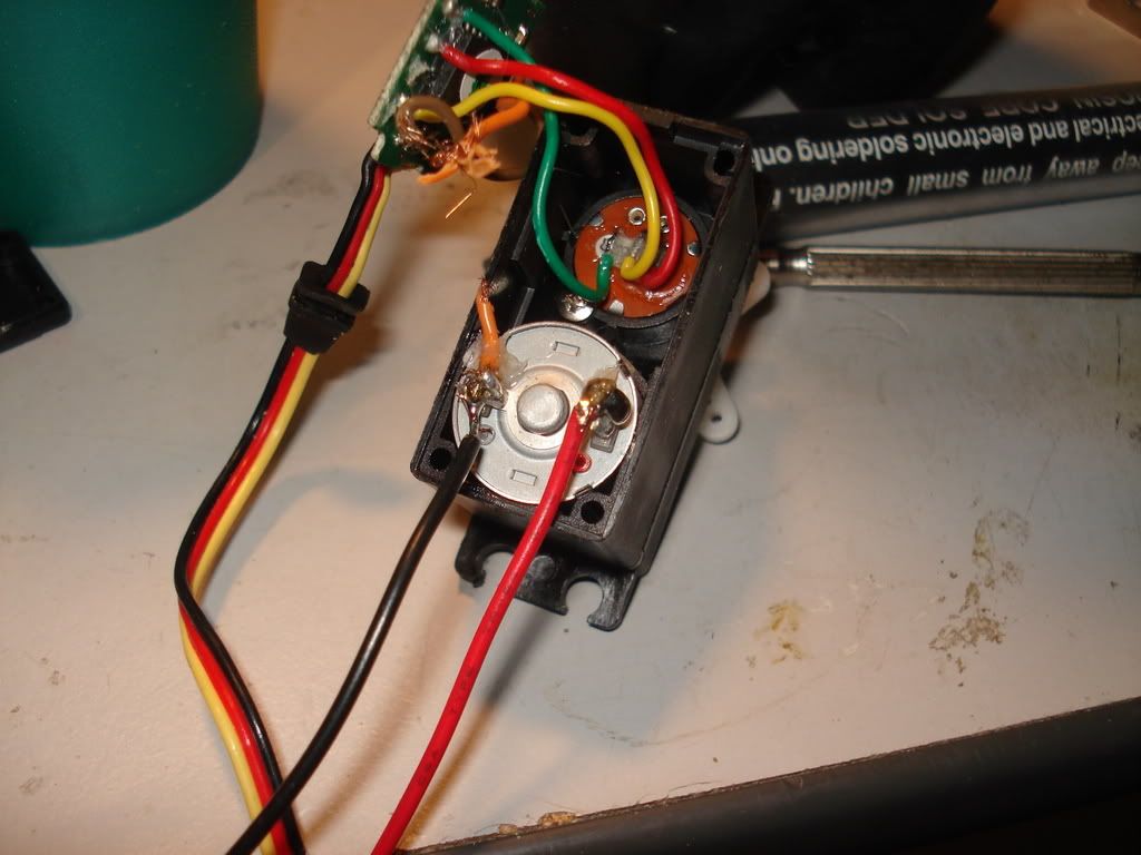
Attach the connector featured to the servo
Attach the servo connector to the pipe connector and tighten them together.Then mount the servo the PVC pipe arm of the right arm using screws or hotglue.
Hotglue the motorized wheel to the bottle holder on an angle so that the wheel brushes against the cap of the bottle.
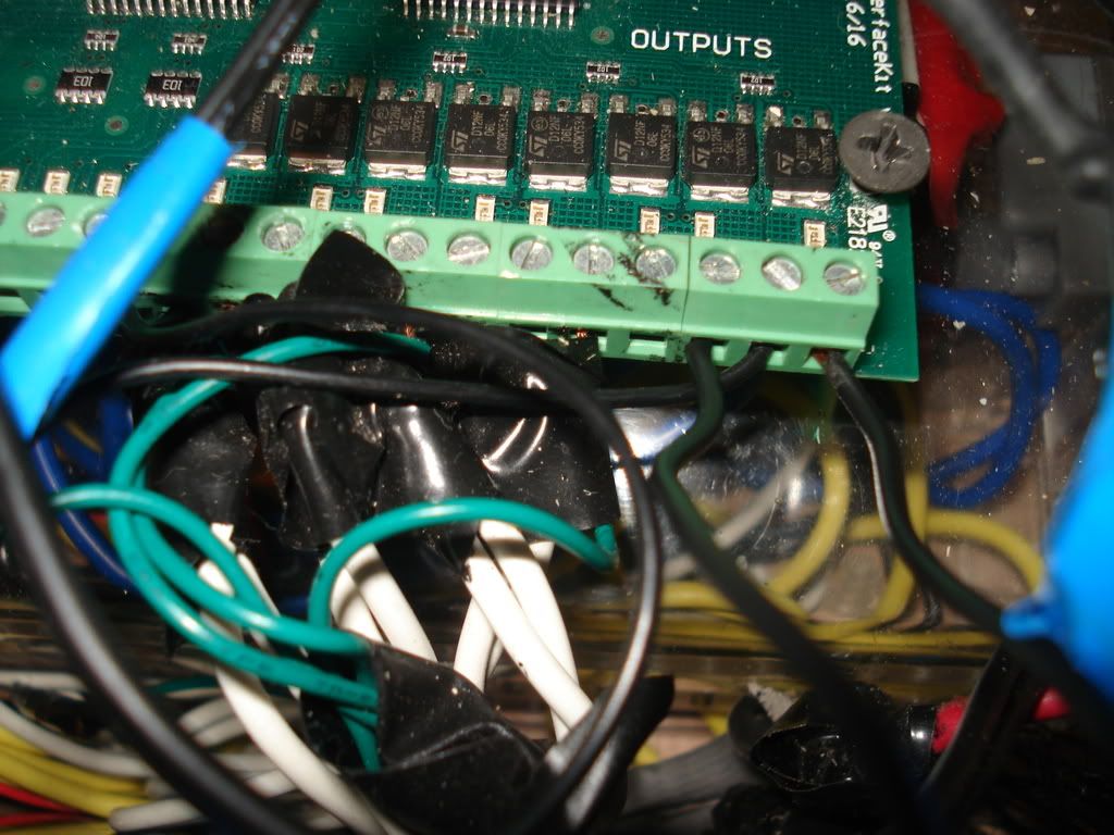
Solder on longer wires to the motorized wheel . Connect the red wires of both the servo motor and the motorized wheel to the positive terminal of the 6V batttery. Connect the black wire of the servo to Output #8 of the Phidgets. The black wire of the motorized wheel should be connected to Output #9.A cup can be attached on a L bracket if you want to add one.
Everything should be wired up now and now you should clean up the wires - that means tape them up, wire tie them , etc. Just make it less messy to work with. Heres what you should have :
The robot head for your butler robot can be whatever you want . I decided to make a dome shaped head with one eye. Here are the instructions for the robot head that I made:
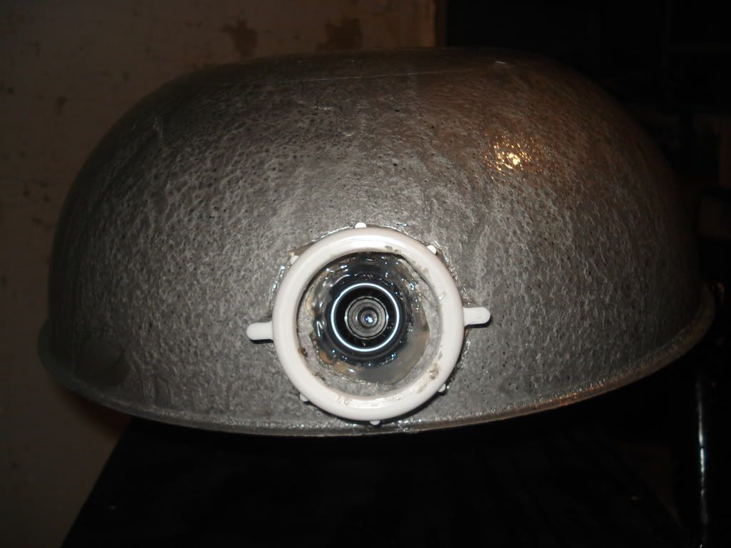
Get a 12" diameter cake cover and if its not silver yet , then spray paint it silver.

Now find a soldering iron that you don't mind destroying. ( you can actually just clean it up afterwards it doesn;t really destroy it)Plug in the soldering iron and wait for it to heat up.
Now find one threaded PVC connector ( 1.5" diameter is what I used).
Hot glue that piece to the silver dome in the place where you want the eye. Now the soldering iron is nice and hot you need to slowly melt a hole inside the PVC piece you just glued. Make sure you don't melt the actual plastic piece.
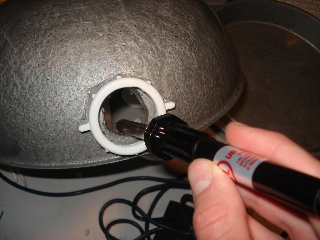
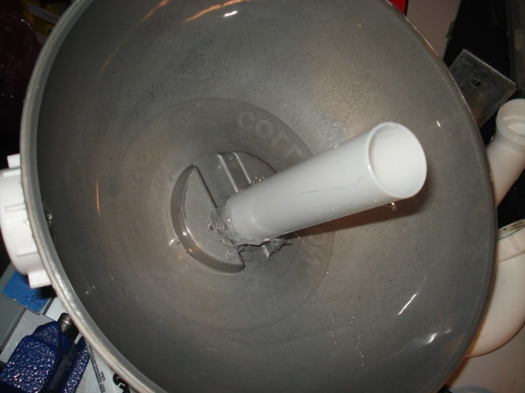
After you made your hole , wet the soldering iron with a sponge and unplug it , letting it cool. Take some PVC pipe ( I used a 7" , 1.5" diameter PVC pipe) and hot glue it to the bottom of the cake cover as shown. Make sure the PVC is attached securely.
Find that webcam that you will dedicate for this butler robot ( I used Quickcam Pro 4000 ) and glue it so that the lens of the camera is looking through that hole we melted.
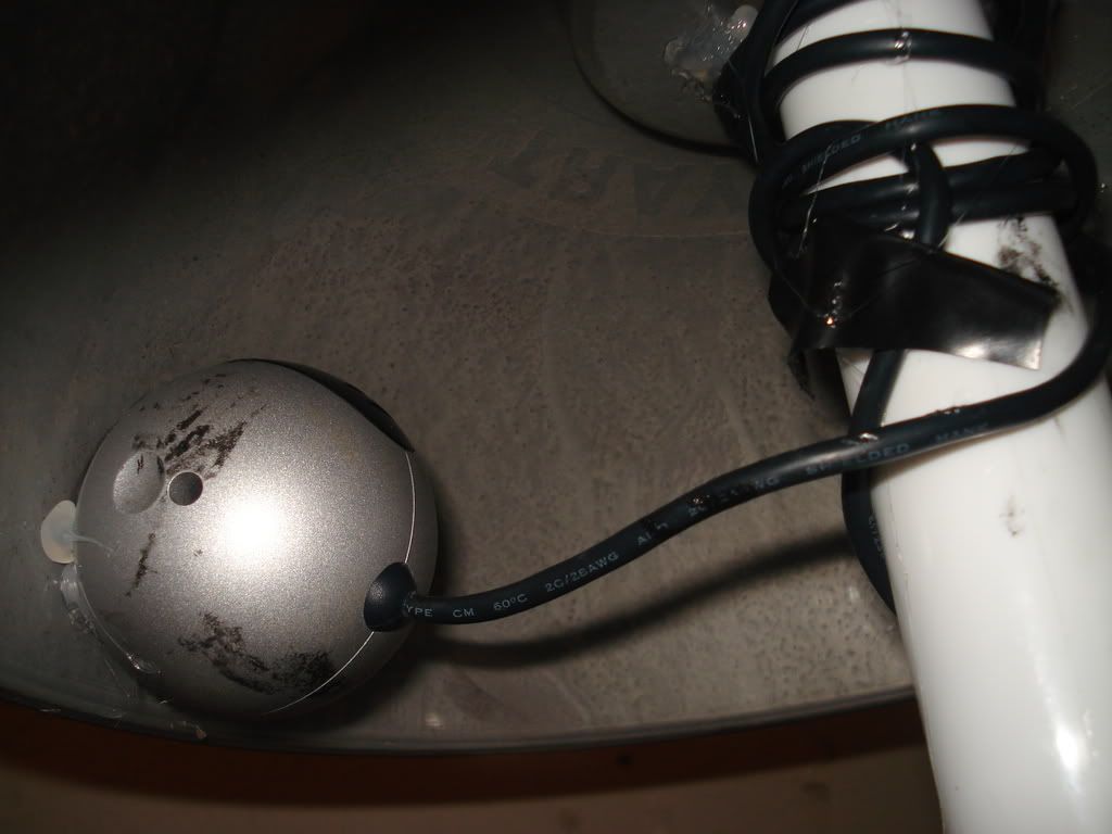
Now the glue the other end of the PVC pipe to the center of the top piece of the wood platform we made.Cool head isn't it?
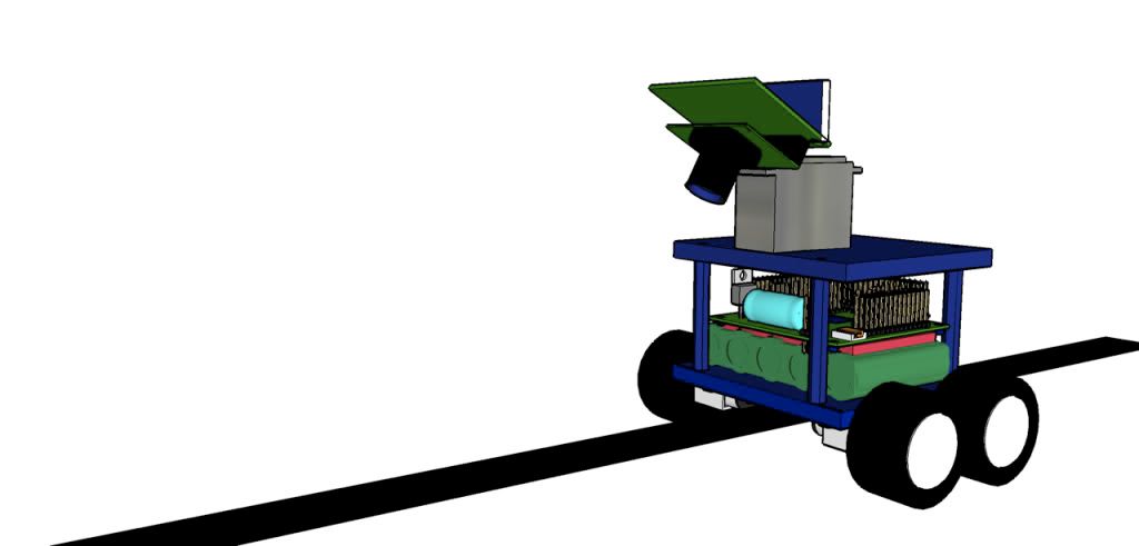
After the bottom is completely assembled and the robot is actually starting to like like a robot, we have to build the upper body , which is the part that will really define the butler robot.This stage will also require the most amount of materials.
I used:
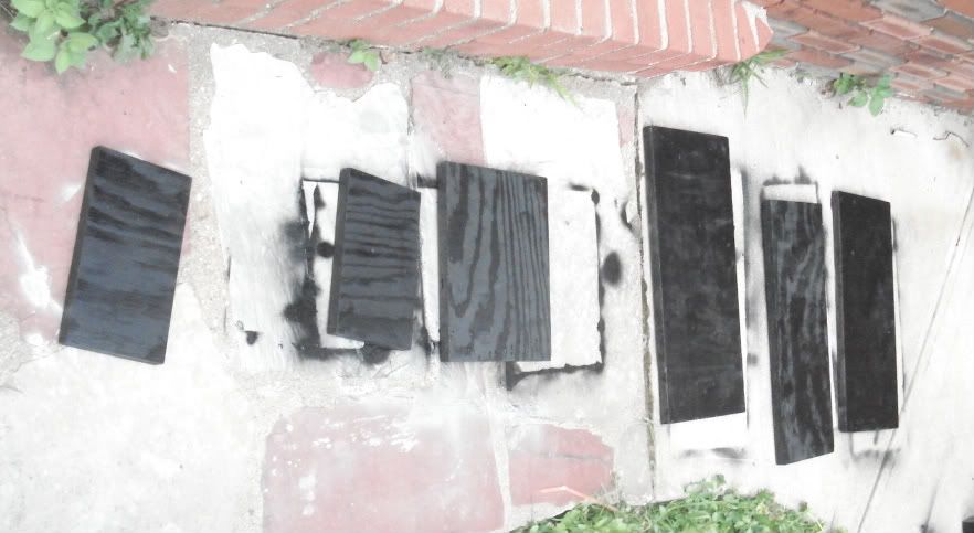
Cut those materials and lay them outside on the floor. Take out a canister of black spray paint and prepare to paint!
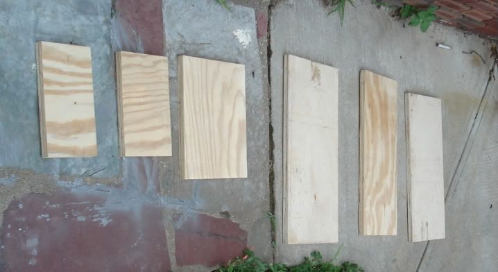
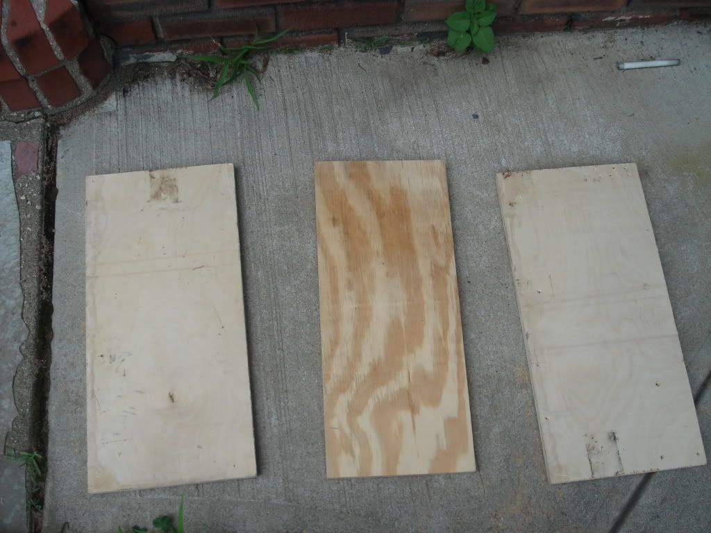
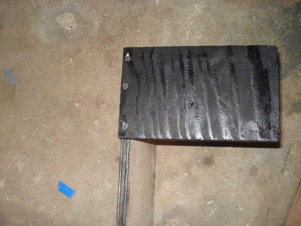
Now take your canister of black spray paint and spray all the boards with a nice layer of black paint. Be sure to wear latex gloves so that you don't get your hands dirty.
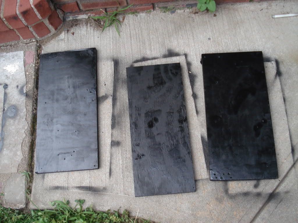
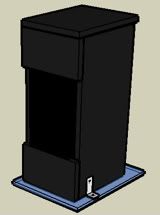
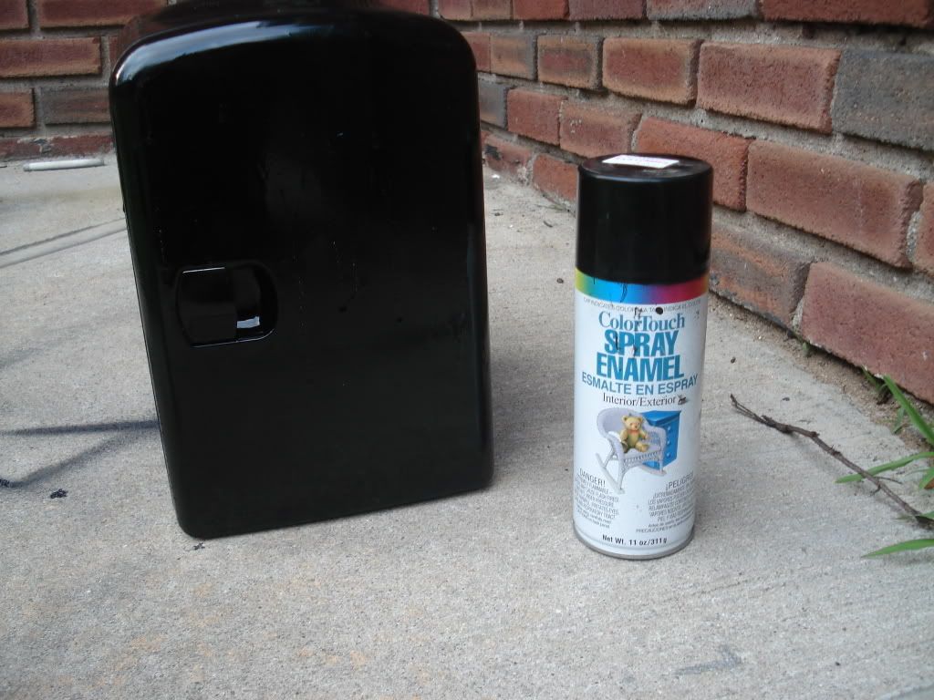
Let the painted wood dry and now get ahold of the mini -fridge. If it isn't black already then spray paint that as well.
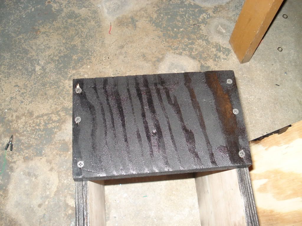
Attach the 5.5" x 9" piece to one of the 10" x 21" pieces as shown in the picture below.
Grab the other 10" x 21" piece and attach it to the other end of the 5.5" x 9" piece.
Now attach the 5" x 9" piece to the other end of the wood.
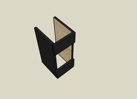
Stand up the wood that was all connected together so that the 5.5" x 9" piece is on the bottom end.
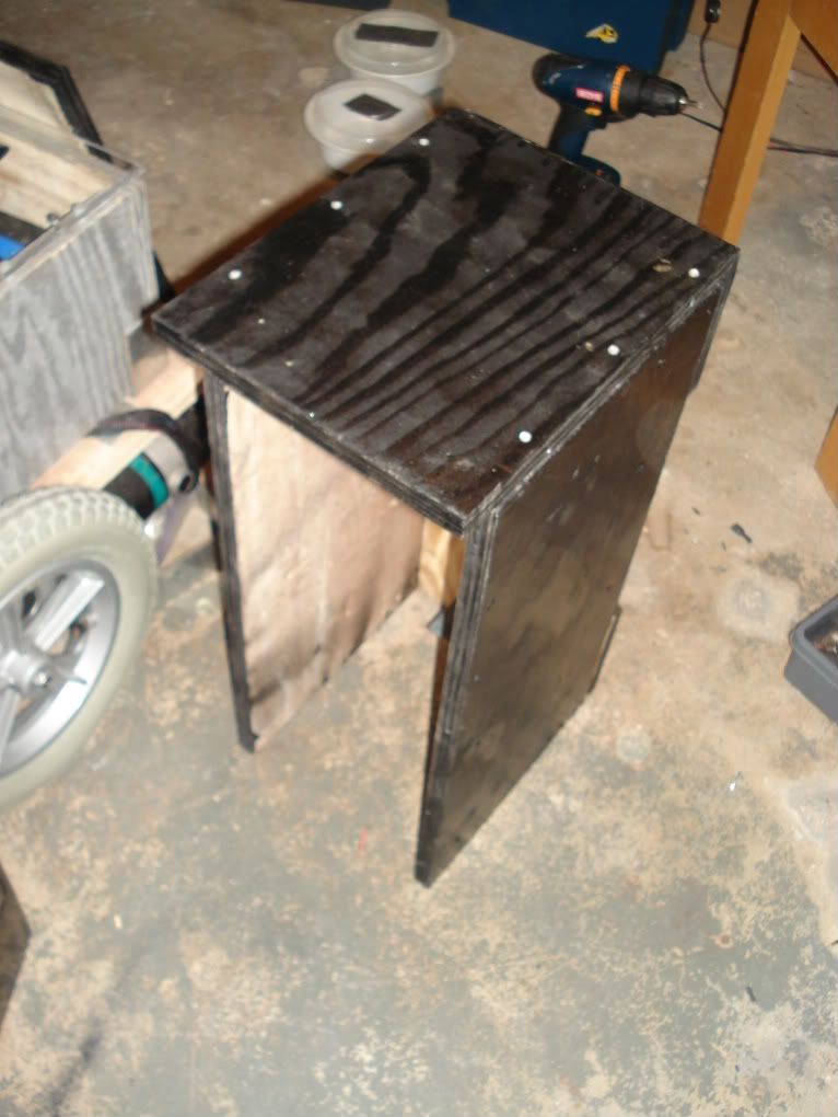
Take the 9" x 11.5" wood and screw it in to the top as show in the picture.
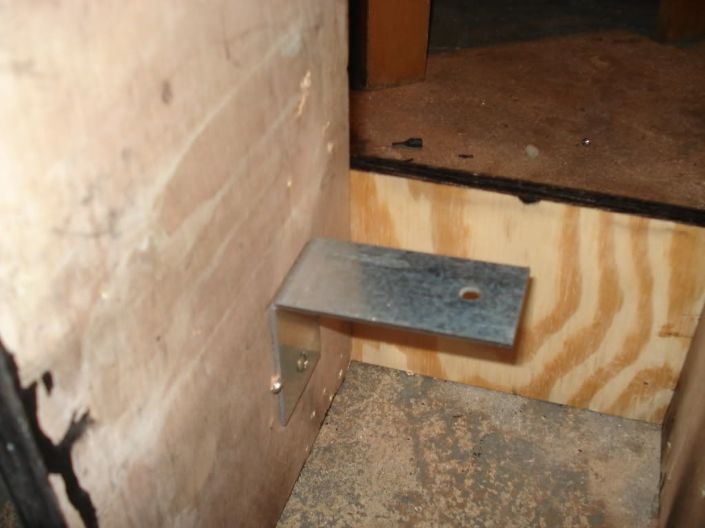
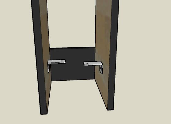
Take two L brackets and connect it so that the top of the bracket is 5" above the floor.
Take that mini-fridge and lay it down on top of the L brackets we just put up.
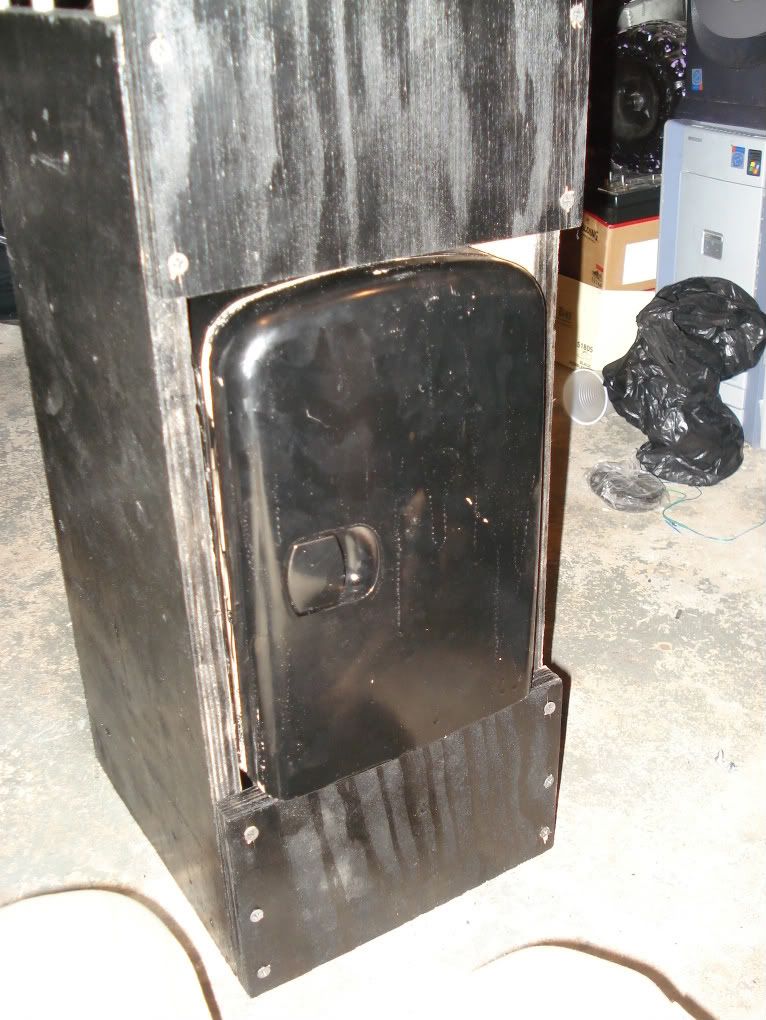
To secure the mini-fridge in place use a hot glue gun to glue the sides of the minifridge to the wood.
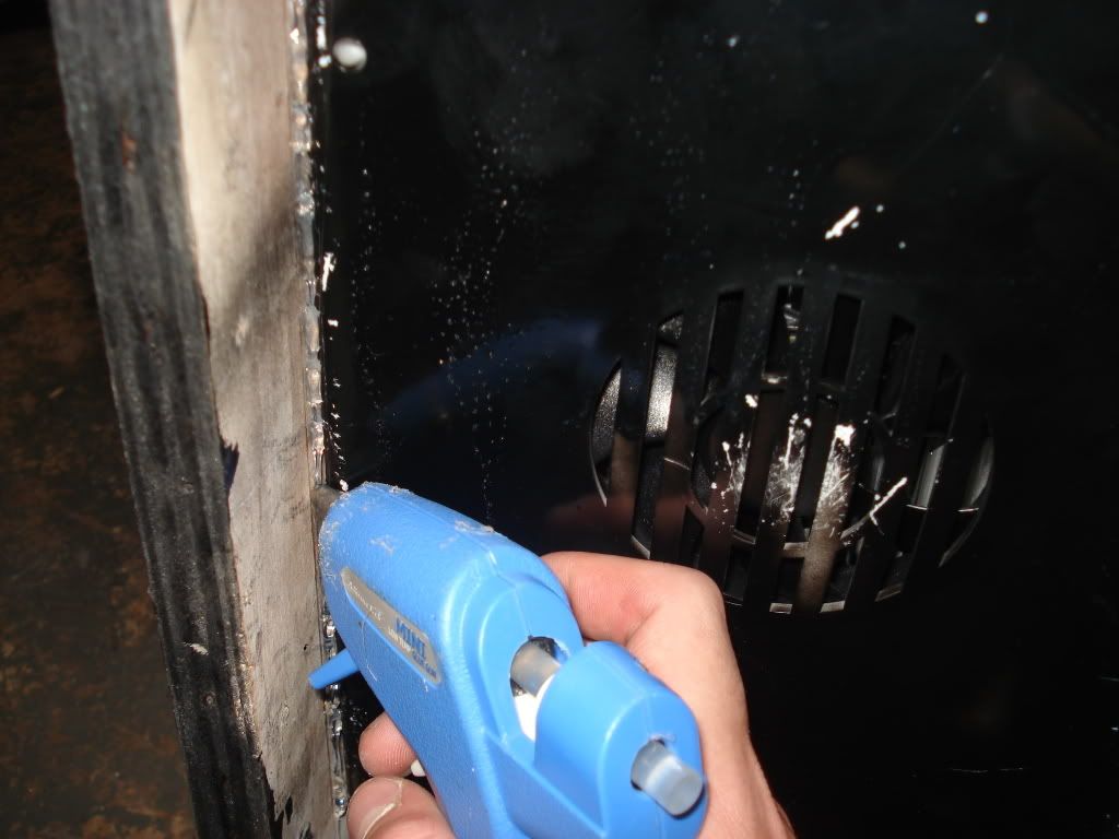
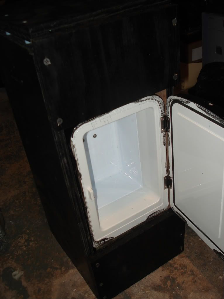
It should be secured and shouldn't wobble in there. Make sure that you have enough clearance to opne the fridge door.
The mini-fridge should have two black wires coming out from the back. Connect the end of one wire to the positive terminal of the 12V battery and the end of the other wire to the negative terminal. Now whenever the robot turns up the minifridge will be on.

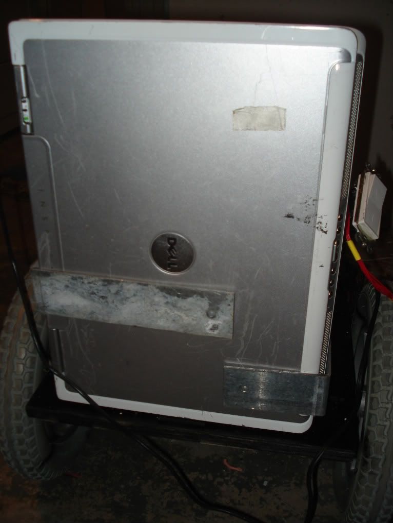
The laptop that I dedicated to Chives was an old one I had and had a 17" screen. Lay the laptop that you have vertically on the space that is in back of the chassis and secure it with L brackets.
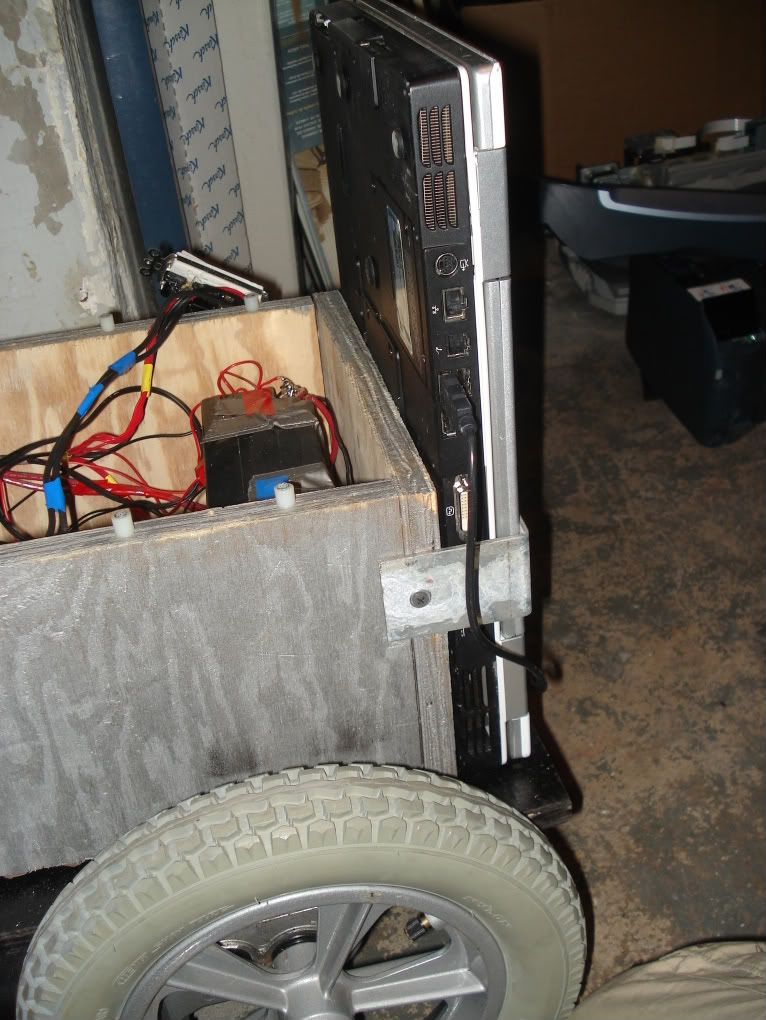
Unscrew the plexiglas cover that we put on the motor enclosure place it on the floor . Now put the wooden box we just built on top of it ( aligning it so that its in the center). Secure the wooden box to the plexiglas using two L brackets.