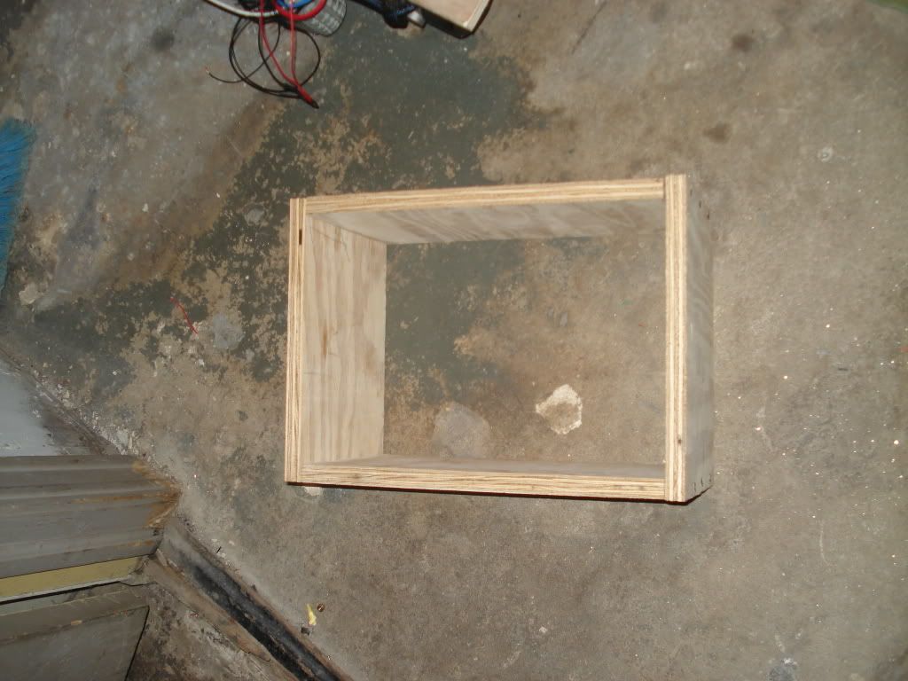
After the chassis is complete we have to make an interface to the motors so that we can control it from a laptop.
The two best methods to control a motor are using a MOSFET motor driver or using a relay. Since I am all about making a robot from common parts and taking advantage of everything available , I used relays. The only downside of a relay is that they cannot be PWMed , which in plain english means you can't have speed control with relays.
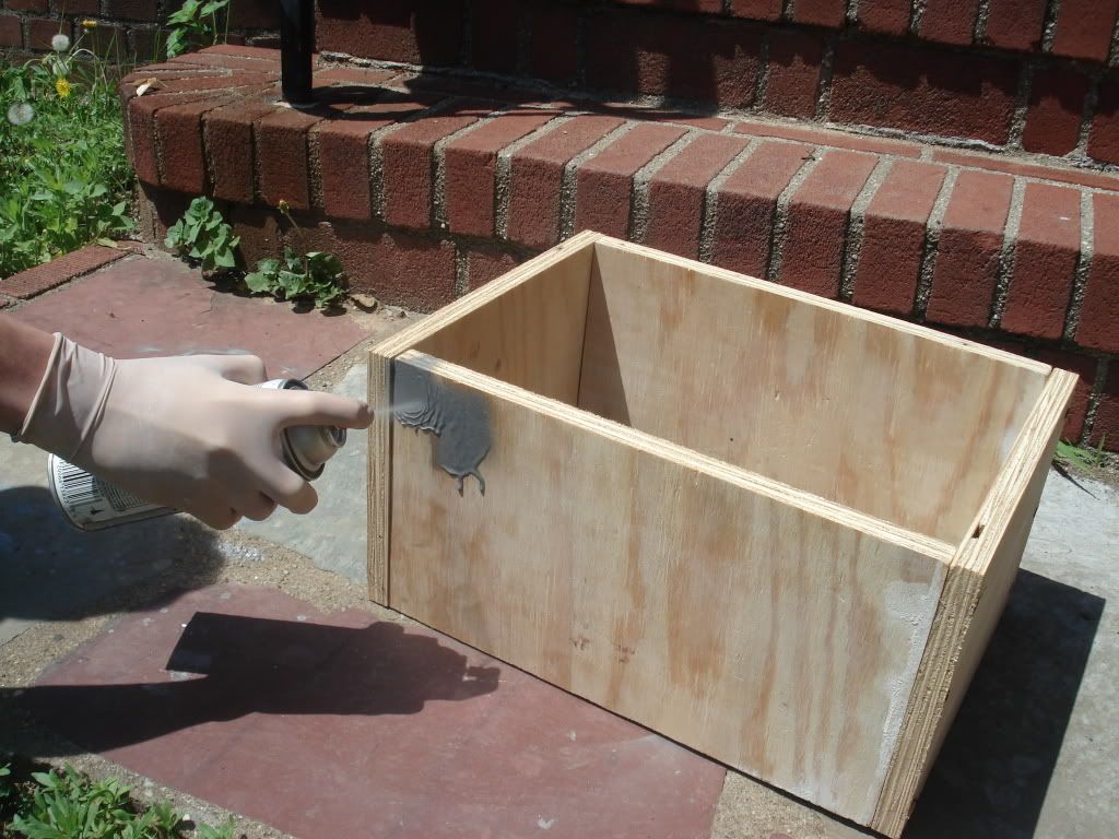
For those who have 125 dollars to spend on motor interface , they can get this
For the majority who dont have that cash to spend, you guys will use automotive relays. The relays I used can be found here. Make sure that you get this socket also. The socket is awesome because it has color coded wires AND it allows you to replace relays easily. You need a total of 8 relays and a total of 4 dual relay sockets.


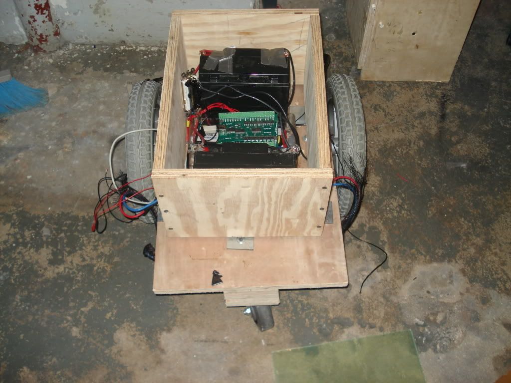
The motors will be powered by either one or two 12V lead acid battery(ies) OR buy two 6V batteries. The battery(ies) that you buy must be able to provide at least 20AH each. If you decide to go with two 12V batteries you wire the batteries in parallel, if they are two 6V batteries then you wire them in series. If its only one 12V battery then obviously you just directly connect wires to the battey without any hitch.

The relays need their own separate supply of 12V to actuate them ( not really needed, you can use the lead acid batteries for this also but its not really good practice to use one source for driving and and being actuated at the same time on a relay ) . What I did was just use eight AA batteries wired in series and then later I switched out the AA batteries for a 12V rechargeable NiMH battery pack . Just make sure they give out 12V total after wired in series.
Step 1: Know what everything does - the relays ,Phidgets interface, and the batteries
Before we actually start making the relay motor controller circuit let's examine what a relay is and how it works.
Read the HowStuffWorks Article on Relays.
You should now understand that a relay is an electromagnet and a switch, and when the electromagnet has electricity running through it the switch closes, but otherwise the switch is open. The switch in our relay will turn on or turn off a motor. You need 4 relays to make a motor be able to go forwards and reverse. If you want to understand how that works have a look at this page.
The electromagnet will be turned on by a neat piece of hardware called a Phidgets Interface Kit. That is the hardware that will interface the computer to the relays. The interface board consists of 16 inputs and 16 outputs. Right now we are interested in the digital outputs. The outputs are just digital switches that switch to ground.

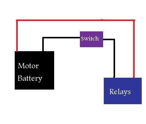
So lets look at the schematic below. Lets pretend that the switch was on the lower line and not the upper one. If the switch was on the lower line then when it was pressed it would let current flow and the LED would light. The Phidgets electronically "press" that switch and close the circuit. Instead of the LED we have a relay and so we always apply power to the relay but the ground part is left open. Only when we want to turn on the relay to we send a command to electronically close the ground switch.
***NEED TO UPDATE SCHEMATIC***

Step 2: Wiring the relays for Motor A
You should have 8 relays and 4 dual sockets. Put each relay in its designated socket.
The following steps are only for two dual sockets ( four relays). The other two remaining dual sockets will get a different wiring which will be detailed in step number three.
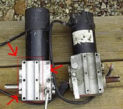
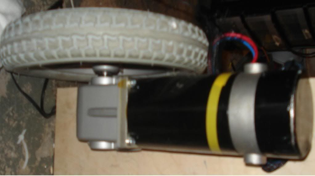
By the way whenever I say to connect the wires , I mean to solder them together. Also, the wheelchair motors should have four wires coming out. There are two thick ones and two skinny ones. Leave the skinny ones alone for now. The thick ones should also be different colors, usually blue and red. If its different colors then just know that I refer to one of the wires as the blue wire and the other one as the red wire.
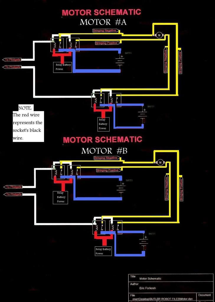
You can either follow the steps below or just read this schematic and follow it. Make sure you follow the shematic by color code.
A. First Dual Socket:
1. One of the relays in the dual socket
Here is the color code key for the wires for the one of the relays on the socket , do this for only ONE of the relays:
BLUE- Connect to power( the positive ) of the motor's batteries. This is the motor's battery's , not the batteries for the relays.
BLACK- Connect to the ground(negative) of the relay's battery
YELLOW- Connect to the blue wire of the motor
WHITE- Leave alone for now
RED - Not used in this project so you could just rip it out or whatever
2. The other relay in the dual socket
Now for the OTHER relay thats in the same dual socket as the other one we just did:
BLUE- Connect to ground( the negative) of the motor's batteries. This is the motor's battery's , not the batteries for the relays.
BLACK- Connect to the ground(negative) of the relay's battery
YELLOW- Connect to the red wire of the same motor used above
WHITE- Connect to the white wire of the other relay in the same dual socket
RED - Not used in this project so you could just rip it out or whatever
Now that we are done with that dual socket , so set it aside. Pickup the second dual socket.
B. Second Dual Socket:
1. One of the relays in the dual socket
Here is the color code key for the wires for the one of the relays on the socket , do this for only ONE of the relays:
BLUE- Connect to power( the positive ) of the motor's batteries. This is the motor's battery's , not the batteries for the relays.
BLACK- Connect to the ground(negative) of the relay's battery
YELLOW- Connect to the red wire of the motor
WHITE- Leave alone for now
RED - Not used in this project so you could just rip it out or whatever
2. The other relay in the dual socket
Now for the OTHER relay thats in the same dual socket as the other one we just did:
BLUE- Connect to ground( the negative) of the motor's batteries. This is the motor's battery's , not the batteries for the relays.
BLACK- Connect to the ground(negative) of the relay's battery
YELLOW- Connect to the blue wire of the same motor used above
WHITE- Connect to the white wire of the other relay in the same dual socket
RED - Not used in this project so you could just rip it out or whatever
STEP 3: Wiring the Relays for Motor B
Now we have finished the motor control for one of the motors. One motor down, one more to go. The other motor will have the EXACT same wiring as the first motor except that YELLOW wires will go to the second motor and not to the first motor ( which we just finished wiring above) . So follow the exact steps for wiring it again , making sure to wire it to the second motor and not the first.
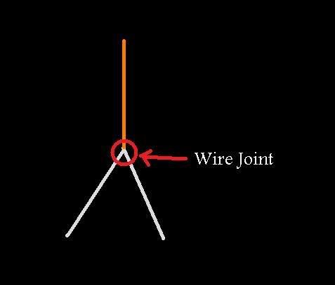
After you are done wiring both motors , locate the white wires. From each wire joint ( point where the white wires were soldered together) you need to connect some wire ( NOT ONE OF THE RELAY SOCKET WIRES) to the joint and then leave the end of that wire alone. If you followed the schematic and not the written steps , then you already did this step.
OK so if you followed all the steps correctly you should have four wires(one per dual socket) which are connected on one side to the relays, but are not connected to anything on the other side. You should also have a ton of wires everywhere. A good idea now is to organize the wires. Grab some labels and start labeling whatever you feel is important to label. Also get some wire ties or string and tidy up.
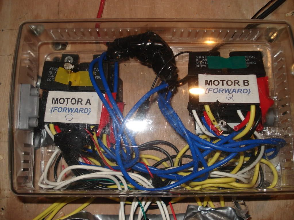
STEP 4: Enclosing the Relays and Labeling
I put both my relay circuits in a nice plastic box and closed it up. This protects the relays and also looks nice as well. Notice how neat it looks! I labeled each individual relay. Disregard the words "forward" on the label for now, we will deal with this all later.
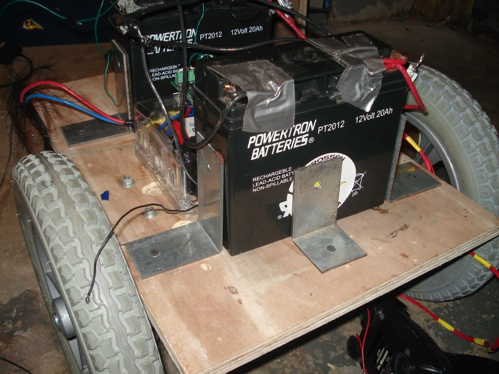
STEP 5: Mounting the batteries
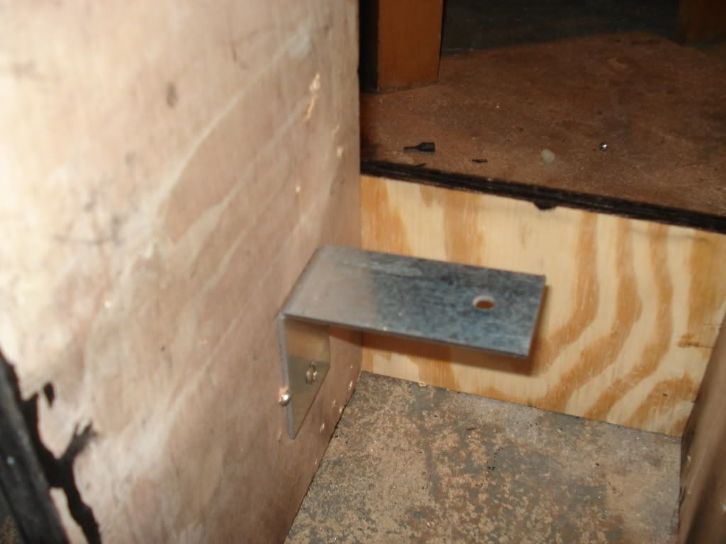
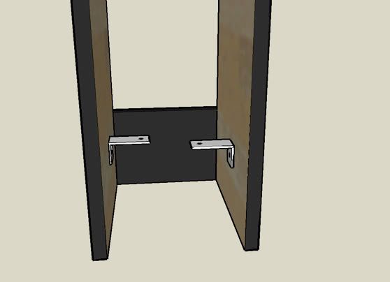
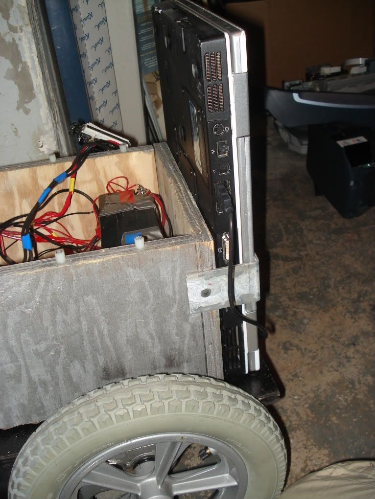
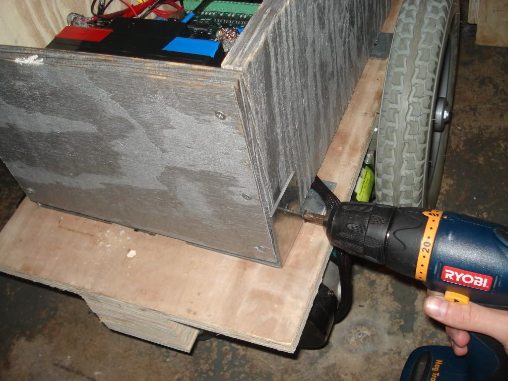
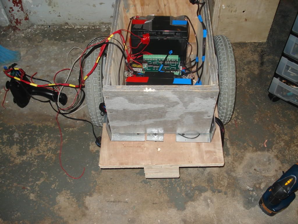
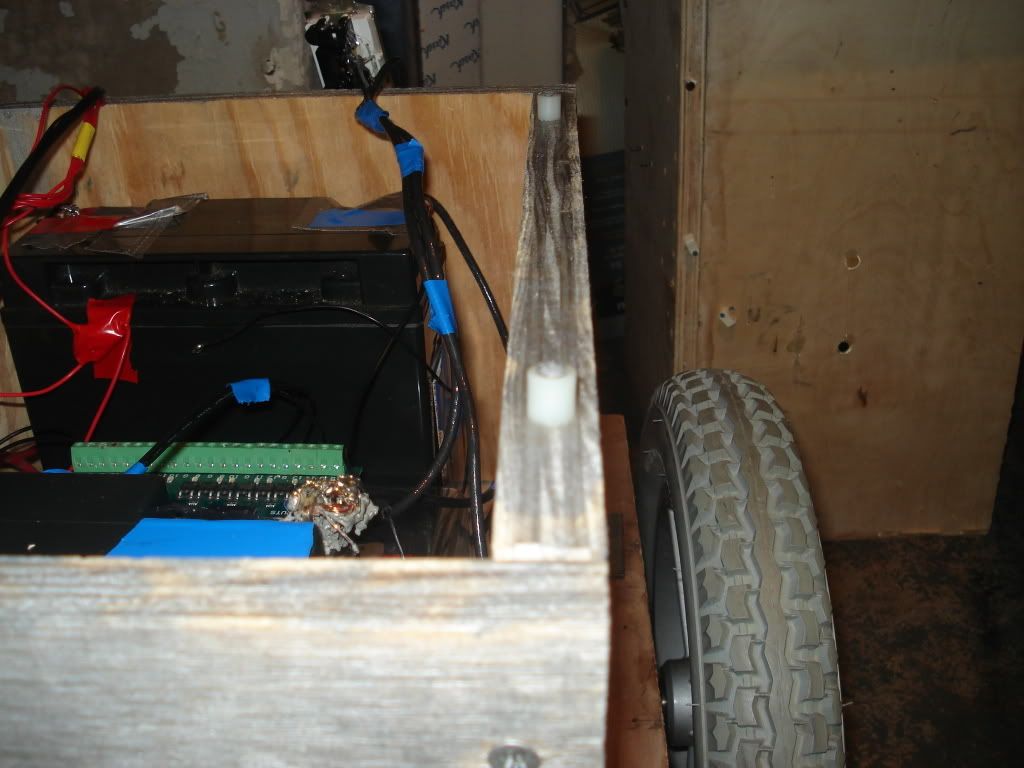
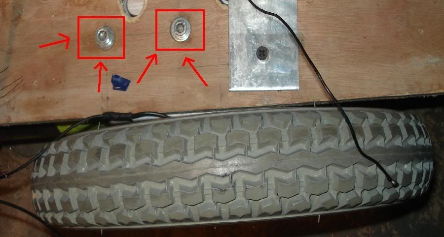
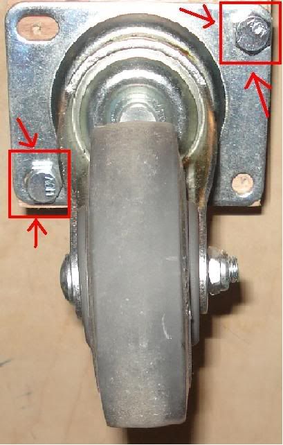
If you haven't done so already , mount the batteries. Use L brackets to hold the batteries in place. L brackets are 90 degree brackets of metal that can be found in all hardware stores ( like Home Depot, Lowes, etc.) Just use the L brackets like I used it below to fasten the batteries to the chassis. Make sure the batteries are fastened tightly and don't move, because while the robot is moving you don't want heavy objects like batteries falling out. Also, notice that I put duct tape to cover the battery's terminals. You should do the same because you want to have the battery's terminal covered at all times to prevent short circuits.
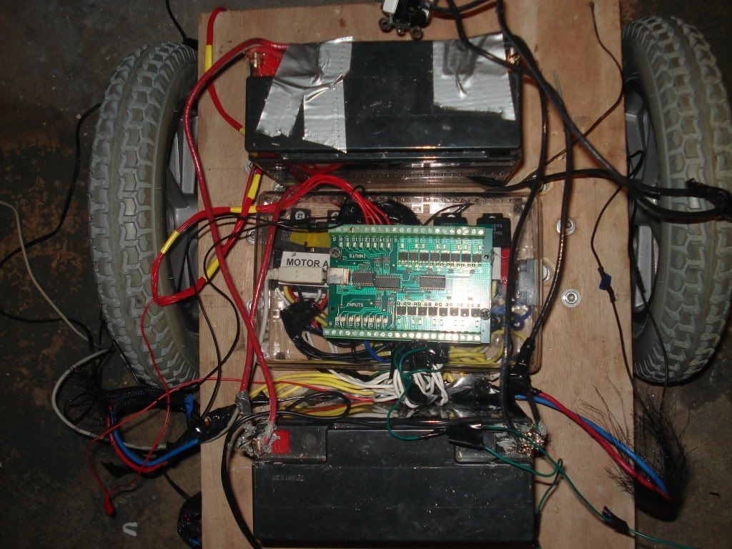
STEP 6: Connect the wires to the Phidgets
Remember the four wires you have from the wire joint from the relay? Now its time to connect them to the Phidgets. Connect the wires to the Phidgets output ports 0 - 3. Each wire getting its own terminal, order doesn't really matter. Also , connect a wire to the relay battery's ground connection ( negative side) and connect the other end to the two Phidgets terminals closest to output terminals 0 - 3 , they are marked "G". This assigns each output of the Phidget to its own dual relay.
STEP 7: Mount the Phidgets
To mount the Phidgets just stick screws or nails through its mounting hole and into the top of the plastic box which encloses your entire relay circuit. If you don't like that , then just mount it anywhere as long as the wires aren't getting to tightly pulled.
STEP 8: Connecting the Kill Switch
Wheelchair robots are very powerful machines, if something goes wrong and it doesn't stop or something it WILL DO DAMAGE. This is why we need to install a mechanical kill switch. All the switch is , is a standard light switch. The switch should have either two wires or two terminals on the side of it. Just cut the negative wire that is going from the motor's battery to the relays. Now that it's cut , connect a switch in between the two wires. Very simple.